Need some advice?
Leave your details and we will get in touch.
I want to be contacted by an expert1 /

Battery Energy Storage Systems (BESS) are transforming the energy landscape, playing a critical role in the transition toward sustainable and resilient power infrastructure. These systems store electrical energy in battery technologies for later use, enabling greater flexibility in energy management, supporting renewable energy integration, and enhancing grid stability.

As BESS deployments accelerate across utility-scale projects and commercial facilities, stakeholders increasingly seek clarity on technical specifications, safety requirements and regulatory frameworks. This is where the experts at SOCOTEC step in: understanding the fundamentals of BESS technology is what we do. From system design and performance metrics to fire safety protocols and compliance standards, we know what is essential for developers, operators, facility managers and regulatory authorities to know and to operate under.
So, whether you are evaluating BESS for a new project, managing an existing installation, or ensuring compliance with safety and performance standards, let SOCOTEC's below FAQs provide practical guidance based on best industry practices and technical expertise.
A Battery Energy Storage System (BESS) is a technology that stores energy in batteries for later use. These systems typically use lithium-iron phosphate (LFP) batteries, which are known for their longevity.
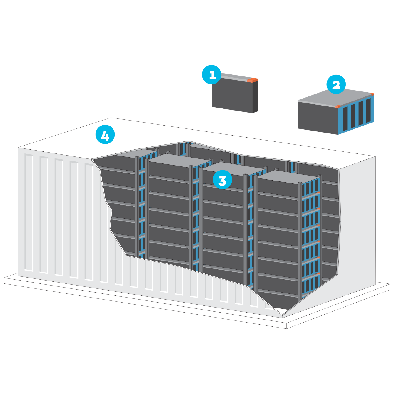
A BESS is built from the ground up, with modules produced by manufacturers which are assembled on-site. The smallest component is a battery cell (1), and multiple cells are grouped to form modules (2), which are then arranged in racks (3), and the collection of racks makes up a complete BESS unit (4).
The physical size of a BESS unit varies depending on its application. Large-scale commercial or industrial units are commonly housed in structures similar in size to shipping containers, while domestic versions are significantly smaller and more compact. The overall capacity of a BESS site depends on the energy requirements it needs to meet; the greater the energy demand, the more units are deployed. These installations are typically located in industrial zones or remote areas where they can safely and efficiently support the electrical grid or local energy needs.
A BESS is designed for long-term operation, with a typical lifespan of approximately 20 years, aligning with the operational lifecycle of the site it serves.
BESS sites present several fire safety risks beyond the battery units themselves. These include potential hazards from transformers, switch rooms and power conversion systems that form part of the overall installation.
However, the most significant risks specific to BESS units are fire, explosion and the release of toxic gases during thermal runaway. Thermal runaway occurs when a battery fails, whether mechanically, thermally or electrically, and triggers a self-sustaining chemical reaction. This process is particularly dangerous because, even after a fire has been suppressed, lithium-ion batteries can spontaneously re-ignite hours or even days later due to the self-feeding nature of the thermal runaway reaction.
From a regulatory perspective, the UK currently lacks comprehensive design guidance specifically for BESS installations. While the National Fire Chiefs Council (NFCC) has published helpful guidance on grid-scale battery energy storage, it does not address all critical design considerations. At present, NFPA 855 (a US-based National Fire Protection Association standard) provides the most comprehensive and robust set of requirements for designing and operating BESS installations safely.
Yes, BESS units undergo rigorous testing to evaluate their fire safety performance. The primary test method used internationally is UL 9540A, in line with NFPA 855, which comprehensively assesses how individual cells, modules, and complete units perform during fire conditions and thermal runaway.
Following successful testing, BESS systems should be certified to UL 9540 standards. This certification provides assurance that the system has met established safety requirements and performed adequately under controlled fire test conditions.
It is important to note that whilst UL 9540A testing and UL 9540 certification are widely recognised internationally, the UK currently does not have its own standardised testing protocol specifically for BESS systems.
Fire suppression systems in BESS units are typically integrated into the manufacturer's design, and in some cases, fire engineers may select from several options provided by the manufacturer. A common suppression method for BESS units involves sprinkler heads connected to a dry pipe system, inert gas or aerosol suppression.
When it comes to firefighting strategies, the current approach focuses on cooling the surrounding areas to prevent fire spread to adjacent BESS units on site. It is important to note that flooding the containers is not recommended, as this can lead to environmental contamination and electrocution of the emergency responders. Furthermore, extinguishing visible flames does not necessarily stop the thermal runaway reaction, which can continue or re-ignite even after initial suppression efforts.
This conservative firefighting approach prioritises containment, cooling the affected areas and protection of neighbouring assets whilst recognising the persistent nature of lithium-ion battery fires and their potential environmental impacts.
Proper site configuration is essential to prevent fire spread both within the BESS installation and to neighbouring properties. The design approach typically follows prescriptive separation distances outlined in established guidance documents, particularly the NFCC guidance and NFPA 855.
The risk of fire spread to adjacent sites is significantly influenced by the quantity of electrolyte stored in each BESS unit. This is because the energy released during a thermal runaway reaction is predominantly derived from the electrolyte combustion.
To accurately assess fire spread risk, once the total electrolyte quantity is determined, a comprehensive fire scenario can be established. This enables engineers to calculate the radiative heat flux that would affect surrounding areas during a thermal runaway event.
At SOCOTEC, we have developed a sophisticated methodology to quantify radiative heat transmission to the surroundings, accounting also for wind effects. This approach utilises large-scale testing results combined with validated correlations established within the gas industry.
The robustness of this methodology has been recognised by the industry, and it has been selected for presentation at the SFPE Performance-Based Design Conference 2026, reflecting its contribution to advancing fire safety engineering practices for BESS installations.
1: CELLS are the basic devices that make up a BESS. They transform electrical energy into chemical energy and vice versa, thereby enabling its storage.
1: CELLS are the basic devices that make up a BESS. They transform electrical energy into chemical energy and vice versa, thereby enabling its storage.
2: MODULES are sets of cells assembles in a container. They are electrically connected and equipped with a management and monitoring system.
2: MODULES are sets of cells assembles in a container. They are electrically connected and equipped with a management and monitoring system.
3: RACKS are sets of modules connected together.
3: RACKS are sets of modules connected together.
4: CONTAINER. The container, which is suitable for outdoor installation, houses a number or racks and all the management devices necessary for the operation of a BESS, including safety, security, management and control systems.
4: CONTAINER. The container, which is suitable for outdoor installation, houses a number or racks and all the management devices necessary for the operation of a BESS, including safety, security, management and control systems.
1: CELLS are the basic devices that make up a BESS. They transform electrical energy into chemical energy and vice versa, thereby enabling its storage.
1: CELLS are the basic devices that make up a BESS. They transform electrical energy into chemical energy and vice versa, thereby enabling its storage.
2: MODULES are sets of cells assembles in a container. They are electrically connected and equipped with a management and monitoring system.
2: MODULES are sets of cells assembles in a container. They are electrically connected and equipped with a management and monitoring system.
3: RACKS are sets of modules connected together.
3: RACKS are sets of modules connected together.
4: CONTAINER. The container, which is suitable for outdoor installation, houses a number or racks and all the management devices necessary for the operation of a BESS, including safety, security, management and control systems.
4: CONTAINER. The container, which is suitable for outdoor installation, houses a number or racks and all the management devices necessary for the operation of a BESS, including safety, security, management and control systems.

Want to find out more about our Fire Safety Services ?